Prerequisites
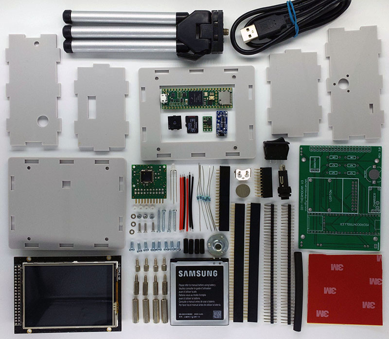
Please refer to the Partlist for the required parts for this guide:
For the tools, you need the following ones in order to follow the assembly process:
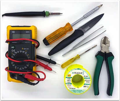
- Soldering Iron
- Soldering Tin
- Cutting Pliers
- Sharp Knife
- Screwdriver
- Tweezer
Eventually you may need a file in case there are any overhanging parts on the header strips.
Building Steps
During the following steps, each tool or part that is added to this step is display in bold text.
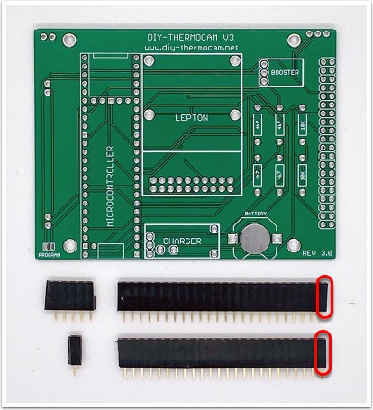
1.
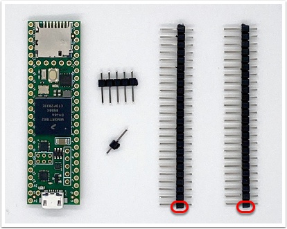
Grab the Teensy 4.1 Microcontroller and the two Male Header Strips. Use the Cutting Pliers to cut one 24-pin strip from each pre-cutted strip, so you have two in total. Make sure that each of those long strips has a flat side as indicated on the image below, so they do not stand out of PCB later. Use one of the remaining strips to cut one 5-pin strip and one 1-pin strip:
2.
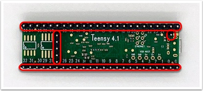
Put the two long 24-pin strips into their marked positions on the backside of the Teensy 4.1 Microcontroller and make sure the flat sides are on the side where the USB port is. Then put in the 5-pin and the 1-pin strip and use the Soldering Iron and some Soldering Tin to solder all strips into their positions. Make sure all strips stand in a right angle towards the PCB of the Teensy before you solder them:
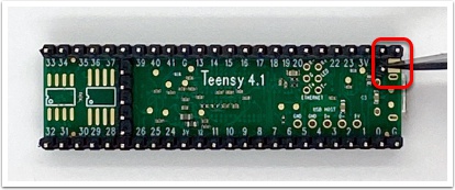
3.
Use the Sharp Knive to cut the connection between the VUSB and VIN pads on the backside of the Teensy 4.1 Microcontroller, so the Thermocam does not power up when the USB cable is connected but the power switch is turned off. Use the Multimeter and its connection checker mode to verify that the two pads are really separated. If they are not, use the Sharp Knive again until there is no connection between the pads anymore:
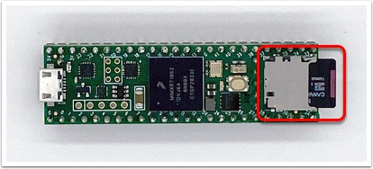
4.
Put the 16GB Class10 microSD Card into its socket on the top of the Teensy 4.1 Microcontroller. This storage can be accessed as a mass storage device over the microUSB cable on a PC. You do not need to format the card beforehand, this will be done in the first time setup later:
5.
Grab the PCB V3.0 and the two Female Header Strips. Use the Cutting Pliers in the same way you did for the male headers and cut a 24-pin strip from each of the pre-cutted strips, so one side is flat as marked on the image. Then cut the remaining 5-pin and 1-pin strips, each from another pre-cutted strip so that you have at least two 10-pin strips left for a later step:
6.
Put the female headers on top of the male headers on the backside of the Teensy 4.1 Microcontroller. This avoids soldering the Teensy directly to the PCB and therefore simplifies any repairs or later adjustments later. In case the 5-pin header does not fit in well, use a File to drawfile its edges:
7.
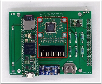
Put the Teensy 4.1 Microcontroller into the marked position on top of the PCB V3.0, and make sure it sits really tight:
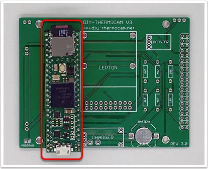
8.
Carefully solder each of the holes on the backside of the PCB:
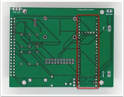
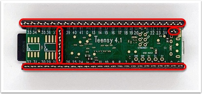
9.
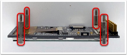
Turn the PCB around and make sure that none of the two long male and female headers of the Teensy 4.1 Microcontroller do stand out over the edges of the PCB. In case they do, use a file to make them flat again, otherwise the enclosure will not fit later.
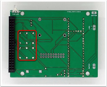
If you have the TP4057 charging module, grab the remaining Male Header Strips and cut one 3-pin strip and four 1-pin strips out of them. Use them to put the blue Charging Module into its position on the top of the PCB:
In case you have the TP4056 charging module, follow the images on this page to solder it to the PCB connections.
10.
Turn the PCB around and solder the seven pins, then use the Cutting Pliers to remove the overlapping parts:
11.
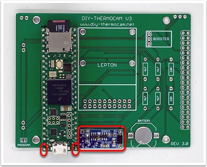
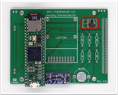
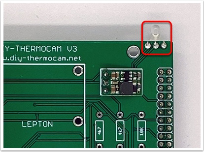
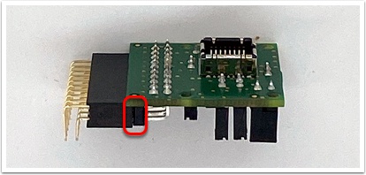
Grab the 5V Step-Up Converter and cut a 3-pin strip from the remaining Male Header Strips. Check which version of the Converter you have. If you have the discontinued U3V12F5, there is a text on the backside of the chip.
For the label reg10a - 0J7032 - @2012, insert the Converter with the components at the top:
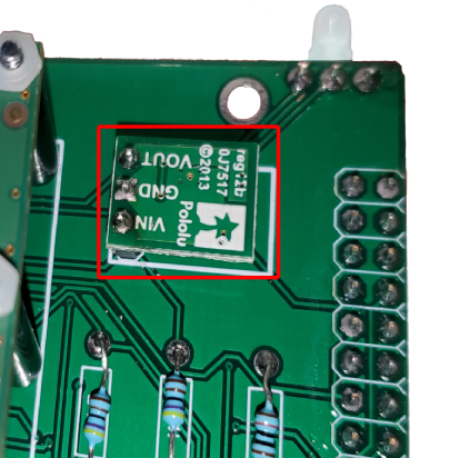
And for the label reg12b - 0J7517 - @2013 or any following year, insert it rotated so that the font is at the top:
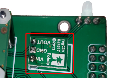
In case you have the new version of the module that is U3V16F5, install it like this:
12.
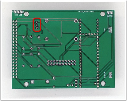
Turn the PCB around and solder the three pins, then use the Cutting Pliers to remove the overlapping parts:
13.
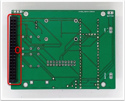
Grab the Display Connector and put it into the marked position on the backside of the PCB by making sure the little notch in the middle is directed towards the inner side of the PCB. Then carefully solder the fourty pins on the backside:
14.
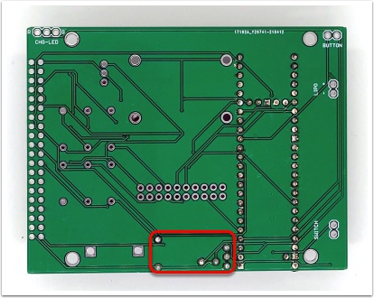
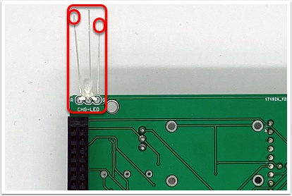
Grab the Charging LED and put it into the marked position on the backside of the PCB, so that the shorter leg is inside the ground hole labeled "G". The LED needs to be soldered with enough lead wire to bend it 90 degrees upward and extend beyond the PCB. Attach the LED at the position in which the LED is already bent:
15.
Turn the PCB around and solder the three pins, then use the Cutting Pliers to remove the overlapping parts:
16.
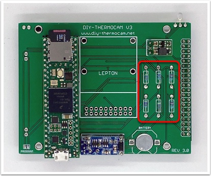
Grab the four 4.7K Resistors and the two 10K Resistors and put them into their marked positions on the top of the PCB:
17.
Turn the PCB around and solder the twelve pins, then use the Cutting Pliers to remove the overlapping parts:
18.
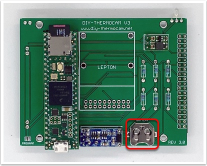
Put the Coin Cell Holder into its marked position on the top of the PCB. Do not insert the coin cell battery yet:
19.
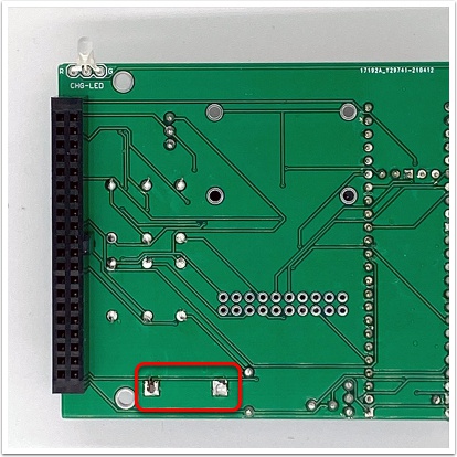
Turn the PCB around and solder the two soldering joins of the coin cell holder:
20.
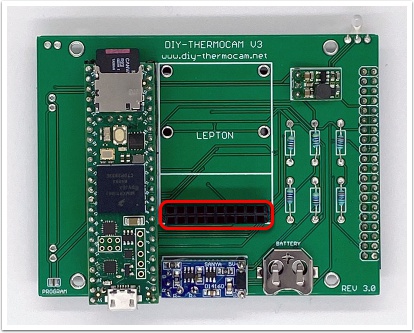
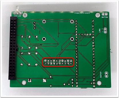
Grab the remaining piece of the two Female Header Strips and cut them into two 10-pin strips that can be inserted into the position marked below:
21.
Turn the PCB around and solder the twenty pins:
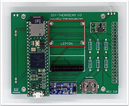
22.
Grab the four Screw M2x18 put them into the marked positions on the PCB:
23.
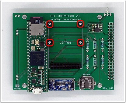
Turn the PCB around and make sure the screws do not drop out. Grab the Red Lipo Protector and If desired, trim excess from the Lipo Protector with scissors before removing any protection foil. It just needs to be slightly bigger than the Lipo battery. It's much more difficult to cut once the protection foil is removed. Then remove the protection foil from one side and glue it to the back of the PCB. Make sure it does not stand over the two marked holes:
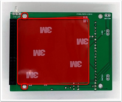
24.
Grab the four black Standoff M2x12 and put them on top of the four screws:
25.
Grab the Lepton Breakout Board V2 and put the right-angle Lepton Header into it. Make sure there is a tight connection between both as indicated on the image:
26.
Put the Lepton Beakout Module V2 on top of the four screws and insert the Lepton Header into the female headers on the PCB. Make sure everything sits tight, then secure it with four Nut M2 Plastic:
27.
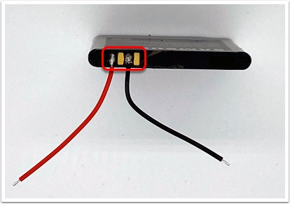
Grab the Lithium Polymer Battery, one Red Wire and one Black Wire. Make sure the battery is aligned as on the image below, then solder the red wire to the plus pin and the black wire to the minus pin by applying some solder tin two both pads:
28.
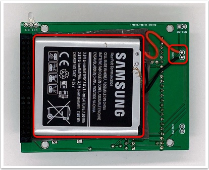
Remove the second protection foil from the Lipo Protector and push the Lithium Battery against it. Then solder the red wire to the plus pin of the connection point labeled "LIPO" on the backside of the PCB, and the black cable to the minus pin:
29.
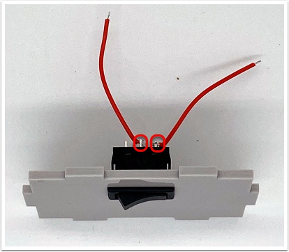
Grab the first side part of the Enclosure and the Power Switch. Insert the switch into its position by aligning the enclosure part as on the image below. Grab the remaining two Red Wires and solder them to the middle and right pin of the switch:
30.
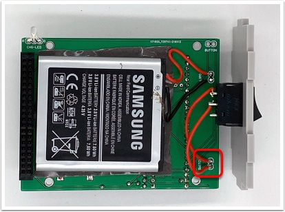
Solder the two red wires to the pins on the PCB labeled "SWITCH", the direction does not play a role. Solder the wires perpendicular / horizontal to the switch, as there will be very little clearance once assembled, and ensure that enough insulation stays in tact to avoid shorting the two wires if they cross. Optionally, you can use self-fusing silicone tape to ensure enough insulation (not shown on the image):
31.
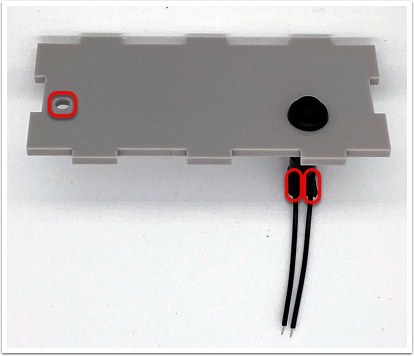
Grab the upper side of the Enclosure and the Push Button. Remove the plastic ring from the push button, put it through the hole and make sure the enclosure part is aligned as display on the image, so that the charging LED hole is closer towards you. Then secure the button with the plastic ring and solder the two remaining Black Wires to each pin of of the push button. Finally use the two Shrinking Tubes to cover the pads. Make the heat shrink tubes as small as needed to cover the pads, as the button enclosure is a tight fit once the screen is added:
32.
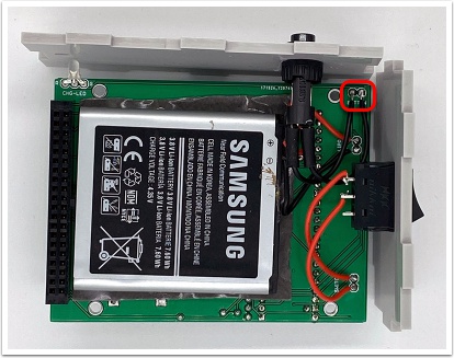
Solder the two black wires to the pins on the PCB labeled "BUTTON". The direction does not play a role:
33.
Grab the 3.2" TFT LCD Touch Display, remove the protection foil from the screen and insert the four Distance Bolt M2.5x5 and the four Distance Bolt M2.5x11 in its holes:
34.
Insert the display into the display header and put the distance bolts through the holes on the PCB. Make sure everything sits tight and none of the wires in between is blocking anything:
35.
Grab the four Distance Bolt M2.5x20 and screw them on top of the four Distance Bolt M2.5x11:
36.
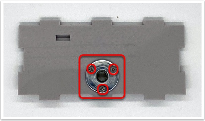
Grab the bottom side part of the Enclosure, the Tripod Socket and the three Screw M2x8 and put them into their positions:
37.
Then secure the bolts with three Nut M2 Metal and use a Screwdriver to make sure everything sits tight:
38.
Grab the front part of the Enclosure and use a Screwdriver to secure it with four Screw M2.5x6. Make sure the front plate is in the right position first, if not turn it upside down:
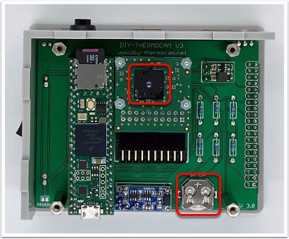
39.
Use a Tweezer or your fingers to carefully put the Lepton2.5, Lepton3.1R or Lepton3.5 into the socket of the Lepton Breakout Board V2. There is only one position it fits in. Make sure it snaps in and clicks on the top and bottom, otherwise there will be no connection to the Lepton possible. Next put the Coin Cell Battery inside the Coin Cell Holder by having the plus on the top as indicated on the holder:
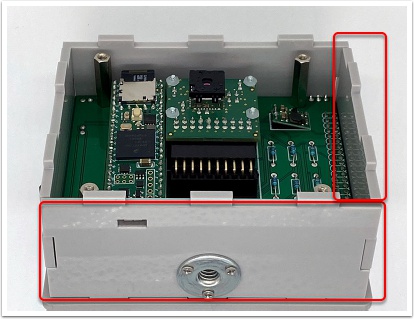
40.
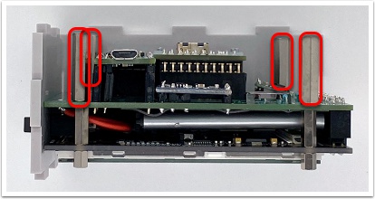
Grab the remaining two sides of the Enclosure and put them into their positions:
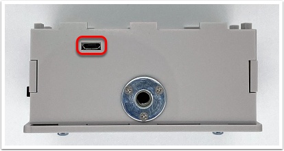
41.
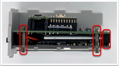
Make sure the USB port of the Teensy 4.1 Microcontroller fits inside the cutout of the bottom side of the Enclosure:
42.
While the backside is still open, you need to flash the latest firmware to the device.
First, get the newest version of the firmware from here and extract the firmware.hex file from the zip archive to your computer.
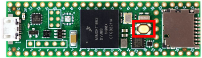
Next, download the Teensy Loader from here and open it. Click the "Auto" button, or choose "Automatic Mode" from the Operations menu. The Auto button should illuminate bright green. Now load the firmware.hex file, it should show up on the bottom side of the GUI.
Press the button on the Teensy microcontroller while it is connected to your PC via USB to start the flashing procedure:
Afterwards, you should see the device rebooting with the logo on the screen. Turn it off to continue with the last steps.
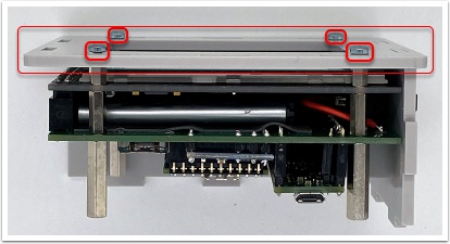
43.
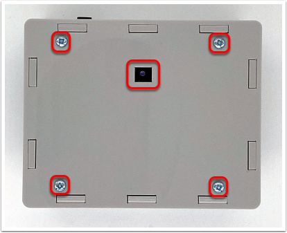
Grab the backside of the Enclosure and put it on top of the four sides. Make sure the Lepton is centered inside the cutout, otherwise turn the backside upside down. Then secure it with the remaining four Screw M2.5x6 by using a Screwdriver. Be careful to not tighten the screws too much, otherwise the backplate may break:
44.
If you want to, you can put the Lepton Enclosure Protector on top of the cutout in the middle of the backside where the Lepton resides. When attached, it can be moved to the top so the Lepton is protected during transportation of the device. Make sure that the sensor does not see the edges of the protector when it is open, otherwise this will leave a vignette heat signature on the thermal images.
45.
Congratulations, you have assembled your own thermal camera! Check out the documentation to learn more about the capabilities of the DIY-Thermocam V3 and also have a look at the open-source software ecosystem, that extends the device capabilities on your computer.
If you have any improvements to this guide, create an issue or a PR with the changes in the diy-thermocam-website repository.